Electronic Capacitor and the Hydraulic Analogy
Easy-to-Understand
Capacitor Models
for Physics & Engineering Students
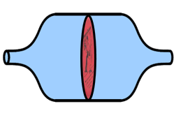
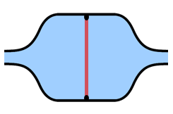
A hydraulic capacitor is a cylinder divided by a flexible rubber sheet. Here's an oblique view and a cross-section side view.
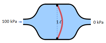
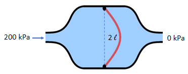
Imagine that the stretchiness and physical
proportions of the rubber sheet are designed so that the
volume of water stored is proportional to the pressure
applied:
The constant of proportionality is called the capacitance, which has units of liters per kPa. In this example, the capacitance is 0.01 liter per kPa.Volume = Capacitance x Pressure
1 liters = 0.01 liters/kPa x 100 kPa
2 liters = 0.01 liters/kPa x 200 kPa
3 liters = 0.01 liters/kPa x 300 kPa
Consider the change over time:
(change in Volume over time) = Capacitance x (change in Pressure over time)
Then you get:
Flow Rate = Capacitance x (dP/dt)where dP/dt means the change in pressure per unit of time.
For example, if you increase the pressure at a rate of 100 kPa per second, the flow rate into the capacitor is 1 liter per second.
1 LPS = 0.01 liter/kPa x 100 kPa/sec
Electronic Capacitor
An electronic capacitor is a set of two parallel metal plates separated by an insulator.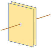
When you apply a voltage across of the capacitor, charge is stored in the capacitor.
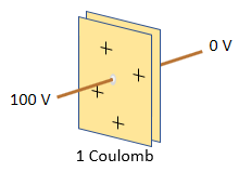
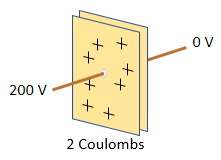
The amount of charged stored is
proportional to the voltage applied:
The constant of proportionality is called the capacitance, and it has units of coulombs per volt, also known as Farads. In this example, the capacitance is 0.01 coulombs per volt, or 0.01 Farad.Charge = Capacitance x Voltage
1 coulomb = 0.01 farad x 100 volts
2 coulombs = 0.01 farad x 200 volts
3 coulombs = 0.01 farad x 300 volts
Consider the change over time:
(change in Charge over time) = Capacitance x (change in Voltage over time)
Then you get:
Current = Capacitance x (dv/dt)where dv/dt means the change in voltage per unit of time.
This is the same equation you see in your physics textbook: i=C(dv/dt)
For example, if you increase the voltage at a rate of 100 volts per second, the flow rate into the capacitor is 1 coulomb per second (1 amp).
1 amp = 0.01 F x 100 volts/sec
Energy Stored in a Capacitor
The energy stored in a charged capacitor is: Energy = 1/2 x Pressure x Volume (hydraulic)For the hydraulic capacitor, the stored energy comes from the pump that pushed the water into the capacitor. The average pressure that pushed in the water is one-half the current pressure (the pressure ramped up from zero to the current pressure as the capacitor was filled).
Energy = 1/2 x Voltage x Charge (electronic)
Similarly, for the electronic capacitor, the stored energy comes from the voltage source that pushed the charge into the capacitor. The average voltage that pushed in the charge is one-half the current voltage (the voltage ramped up from zero to the current voltage).
You can extract the energy by connecting a resistor between the two ends of the capacitor. This causes a current to flow through the resistor. The voltage and current both decay exponentially until the voltage reaches zero and all the energy is dissipated as heat in the resistor.
Conservation of Charge and the Electric Field
Charge is conserved, even as a capacitor is charged and
discharged. When you connect a battery to a capacitor, the
battery draws positive charge from one side of the capacitor,
leaving a deficit or
negative charge on that side, and puts the positive charge on
the other
side. For example, connecting a 100 V battery to a 1 Farad capacitor draws 50 coulombs of charge into the positive side of the capacitor, leaving -50 coulombs on the negative side.
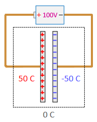
Then the capacitor has a net charge of zero (50 coulombs + -50 coulombs) but a difference of 100 coulombs on the two sides. When the battery is disconnected, the voltage difference remains because the charge is trapped in the capacitor.
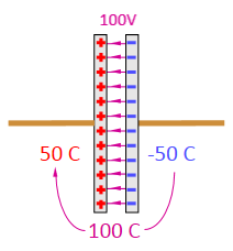
The physical attraction of opposite charges holds the positive and negative charge in place. That's why a capacitor is made with closely spaces parallel plates -- to get the opposite charges as close together as possible, over as large an area as possible.
An electric field exists in the space between the two plates, which causes any charged object in that space to feel a force. For example, a free electron is attracted to the positively charged plate and repelled by the negatively charged plate.
If you short-circuit the two terminals of the capacitor, the charge rushes back from the positively charged side to the negatively charged side, bringing the charge back to zero on both sides.
Dielectric Material Affects the
Capacitance
If an electronic capacitor is configured as two parallel
plates, the
capacitance depends on the area of the plates, the distance
between
them, and the type of material between the plates. Bigger
plates means
more area for storing charge and a higher capacitance. Closer
spacing of the plates means a stronger electric field, which
can hold more charge
and therefore increases the capacitance. A capacitor works fine with just empty space or air between the plates. However, the capacitance can be increased greatly by putting dielectric material between the plates, that is, a material whose molecules are polar (they each have a positive and a negative side), and the molecules have the ability to move or at least turn in place. Liquid water and ice are examples of dielectric materials.
The positive and negative plates attract the negative and positive ends of the molecules, respectively, so the molecules move or turn to face the opposite type of charge on each plate. This has the effect of decreasing the electric field inside the dielectric material but increasing the electric field just outside the material, facing toward the plates. Therefore, the plates see a stronger electric field, and more charge can be stored for the same applied voltage.
Inductor Hydraulic Analogy
Back to Main Hydraulic Analogy Page
Water circuit analogy to electric circuit
from HyperPhysics by C. Rod Nave, Georgia State University
Excellent resource for physics students
Hydraulic analogy, Wikipedia
Brief Wikipedia article, good overview
Understanding Electricity with Hydraulics
Describes hydraulic models for diodes, transistors, and op amps
Circuit Analysis, Khan Academy
Math analysis of electric circuits, including LC oscillator
Crystal radio, Wikipedia
Good info on crystal radio operation and history