Electric Circuits and the Hydraulic Analogy
For Physics &
Engineering Students
Hydraulic Resistor, Capacitor, & Inductor Models
V=IR, I=C(dv/dt), V=L(di/dt)
 Introduction Read |
 Energy, Power Read |
 Resistor (easy) Read |
 Capacitor (med) Read |
 Inductor (hard) Read |
 Oscillator (fun) Read |
Introduction: Charge, Voltage, and Current
Hydraulic systems are like electric circuits:- volume (liters) is like charge (coulombs)
- flow rate (liters per second, or LPS) is like current
(coulombs per second, or amps)
- pressure (kPa) is like voltage (volts)
- energy is pressure x volume (kPa x
liters = joules)
or voltage x charge (volts x coulombs = joules)
- power is pressure x flow rate (kPa x
LPS = watts)
or voltage x current (volts x amps = watts)


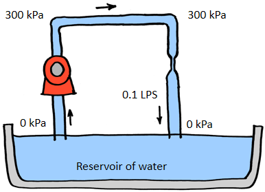
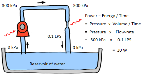
In a hydraulic circuit, a pump brings up water from a reservoir at zero pressure and pressurizes it; this requires energy. The water flows under pressure. When the water under pressure is released, the pressure drops back to zero and the stored energy is released.
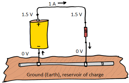
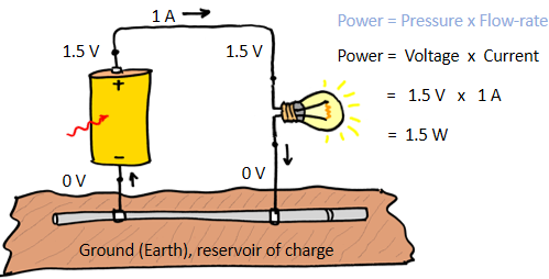
In an electric circuit, a battery brings up charge from ground at zero voltage and raises the charge to a higher voltage; this requires energy. The charge flows under the increased voltage. When the charge is released, the voltage drops back to zero and the stored energy is released.
Energy and Power
In a hydraulic circuit, water under pressure flows through a pipe, with:- Energy = Pressure x Volume
- Power = Pressure x Flow Rate
- Energy = Voltage x Charge
- Power = Voltage x Current
Hydraulic energy is calculated as work (force x distance), for example, a piston pushing against water under pressure.
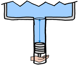
In this case, the force is the pressure multiplied by the area of the top of the piston. Thus:
Energy = Force x Distance
= (Pressure x Area) x Distance
= Pressure x (Area x Distance)
= Pressure x Volume
= 300 kPa x 2 liters = 600 joules
where the pressure is 300 kPa and the the piston displaces 2 liters of water.
Similarly, electric energy is calculated as a force that moves an amount of charge in an electric field, changing the voltage where the charge rests. For example, if you rub a piece of amber with fur, the amber acquires a negative charge. If you put the amber between two metal plates with 100 volts of potential difference, the amber is attracted to the positive plate and repelled by the negative plate.
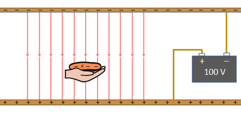
Energy = Voltage x Charge
= 100 volts x 1 coulomb
= 100 joules
(This is ignoring gravity and considering only the electrical force.)
In a hydraulic circuit, a pump operates continuously with a power of pressure x flow-rate to pressurize and move water. When the pressurized water is released and allowed to fall to a lower pressure, the stored energy is also released. In the following diagram, the pump uses energy to pressurize and move the water; the water flowing through the resistor (narrow part of the pipe) drops back to zero pressure and releases the energy as heat.
Similarly, in an electric circuit, a battery operates continuously with a power of voltage x current to "pressurize" and move charge. When the "pressurized" charge is released and allowed to fall to a lower voltage, the stored energy is also released. In the following diagram, the battery uses energy to "pressurize" (force to a higher voltage) and move the charge; the charge flowing through the light bulb drops back to zero voltage and releases the energy as light and heat.
Resistor Behavior
A hydraulic resistor is a narrow section of a pipe that causes the pressure top drop in the direction of flow. Similarly, and electronic resistor is a partial blockage in a wire that causes a drop in voltage in the direction of flow.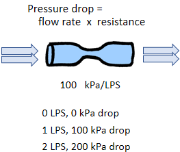
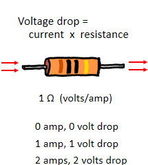
According to Ohm's law, the drop in pressure (voltage) across a resistor is proportional to the flow rate (current) through the resistor.
For an electronic resistor, the constant of proportionality is called the resistance, and the units are volts per amp, or Ohms. For example, a 1-ohm resistor has a voltage drop of 1 volt for 1 amp of current, 2 volts for 2 amps of current, and so on.
You can imagine a similar behavior for a hydraulic resistor. The more water you push through the narrow point in the pipe, the greater the pressure drop across the resistive point.
Flow through a resistor converts potential energy into heat. The rate at which heat is produced is the pressure drop in kPa multiplied by the flow rate in liters per second; or the voltage drop in volts multiplied by the current in amps. In both cases, the power units are Watts.
Capacitor Behavior
Here I compare the behavior of hydraulic and electronic capacitors.
Watch video
Hydraulic Capacitor
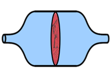
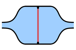
A hydraulic capacitor is a cylinder divided by a flexible rubber sheet. Here's an oblique view and a cross-section side view (the latter is easier to draw).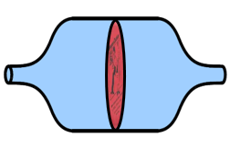
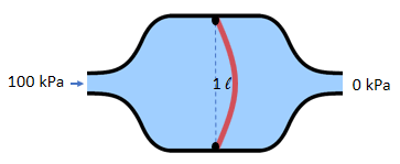
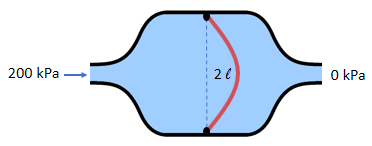
The volume of water stored is proportional
to the pressure applied:
The constant of proportionality is called the capacitance, which has units of liters per kPa. In this example, the capacitance is 0.01 liter per kPa.Volume = Capacitance x Pressure
1 liters = 0.01 liters/kPa x 100 kPa
2 liters = 0.01 liters/kPa x 200 kPa
3 liters = 0.01 liters/kPa x 300 kPa
Consider the change over time:
(change in Volume over time) = Capacitance x (change in Pressure over time)
Then you get:
Flow Rate = Capacitance x (dP/dt)where dP/dt means the change in pressure per unit of time.
For example, if you increase the pressure at a rate of 100 kPa per second, the flow rate into the capacitor is 1 liter per second.
1 LPS = 0.01 liter/kPa x 100 kPa/sec
Electronic Capacitor
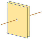
An electronic capacitor is a set of two parallel metal plates separated by an insulator.
When you apply a voltage across of the capacitor, charge is stored in the capacitor.
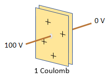
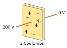
The amount of charged stored is
proportional to the voltage applied:
The constant of proportionality is called the capacitance, and it has units of coulombs per volt, also known as Farads. In this example, the capacitance is 0.01 coulombs per volt, or 0.01 Farad.Charge = Capacitance x Voltage
2 coulombs = 0.01 farad x 200 volts
Consider the change over time:
(change in Charge over time) = Capacitance x (change in Voltage over time)
Then you get:
Current = Capacitance x (dv/dt)where dv/dt means the change in voltage per unit of time.
For example, if you increase the voltage at a rate of 100 volts per second, the flow rate into the capacitor is 1 coulomb per second (1 amp).
1 amp = 0.01 F x 100 volts/sec
Energy Stored in a Capacitor
The energy stored in a charged capacitor is: Energy = 1/2 x Pressure x Volume (hydraulic)For the hydraulic capacitor, the stored energy comes from the pump that pushed the water into the capacitor. The average pressure that pushed in the water is one-half the current pressure (the pressure ramped up from zero to the current pressure as the capacitor was filled).
Energy = 1/2 x Voltage x Charge (electronic)
Similarly, for the electronic capacitor, the stored energy comes from the voltage source that pushed the charge into the capacitor. The average voltage that pushed in the charge is one-half the current voltage (the voltage ramped up from zero to the current voltage).
You can extract the energy by connecting a resistor between the two ends of the capacitor. This causes a current to flow through the resistor. The voltage and current both decay exponentially until the voltage reaches zero and all the energy is dissipated as heat in the resistor.
Conservation of Charge and the Electric Field
Charge is conserved, even as a capacitor is charged and
discharged. When you connect a battery to a capacitor, the
battery draws positive charge from one side of the capacitor,
leaving a deficit or negative charge on that side, and puts
the positive charge on the other side. For example, connecting a 100 V battery to a 1 Farad capacitor draws 50 coulombs of charge into the positive side of the capacitor, leaving -50 coulombs on the negative side.
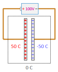
Then the capacitor has a net charge of zero (50 coulombs + -50 coulombs) but a difference of 100 coulombs on the two sides. When the battery is disconnected, the voltage difference remains because the charge is trapped in the capacitor.
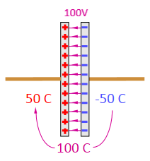
The physical attraction of opposite charges holds the positive and negative charge in place. That's why a capacitor is made with closely spaces parallel plates -- to get the opposite charges as close together as possible, over as large an area as possible.
An electric field exists in the space between the two plates, which causes any charged object in that space to feel a force. For example, a free electron is attracted to the positively charged plate and repelled by the negatively charged plate.
If you short-circuit the two terminals of the capacitor, the charge rushes back from the positively charged side to the negatively charged side, bringing the charge back to zero on both sides.
Effects of Dielectric Materials
Inductor Behavior
Here I compare the behavior of hydraulic and electronic inductors.
Watch Video
Hydraulic Inductor
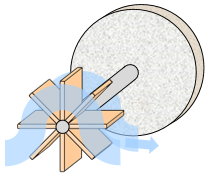
A hydraulic inductor is a water wheel connected through a rigid axle to a heavy stone flywheel, with a housing that forces the water in a clockwise direction when the water flows from left to right. Here's a conceptual view and a cross-section side view:
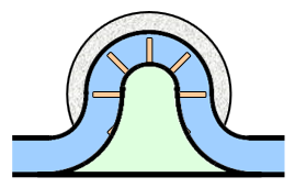
Applying pressure to the inductor presses water against the paddles of the water wheel. This starts the turning of the water wheel and the connected flywheel. As pressure is applied over time, the flywheel gradually turns faster and faster. Once the flywheel is turning, it tends to keep turning even when the pressure is removed, keeping the water flowing at a constant speed in the absence of outside forces.
The momentum of the flywheel is proportional to the flow rate.
Momentum = Inductance x Flow RateThe constant of proportionality is called the inductance. In this example, the inductance is 20 units.
20 kPa-sec = 20 kPa-sec/LPS x 1 LPS
40 kPa-sec = 20 kPa-sec/LPS x 2 LPS
60 kPa-sec = 20 kPa-sec/LPS x 3 LPS
Consider change over time:
(change in Momentum over time) = Inductance x (change in Flow Rate over time)
The change in momentum over time is the same as the pressure applied:
Pressure = Inductance x (dF/dt)The notation dF/dt means the change in flow rate over time (units: liters per second per second).
For example, if you apply a pressure of 20 kPa the inductor, the flow rate increases by one LPS per second.
20 kPa= 20 kPa-sec/LPS x 1 LPS/secondTo summarize:
- Applying a constant pressure of 20 kPa to the inductor
causes the flow rate to increase by 1 liter per second for
each second that the pressure is applied.
- Applying zero pressure causes the flow to continue at a
constant rate.
- Applying a negative pressure of 20 kPa causes the flow to decrease by 1 liter per second for each second that the negative pressure is applied.
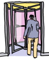
If the people are in a big hurry, they push on the revolving door (apply positive pressure), which causes the door to speed up and gain momentum.
If the people are relaxed and walk through at the same speed that the door is moving, the door keeps turning at the same speed and has a constant momentum.
If some very slow people come through, the door catches up to them and pushes them through (negative pressure), which causes the door to slow down and lose momentum.
Electronic Inductor
An electronic inductor is a coil of wire wrapped around a cylindrical core.
Applying a voltage to the inductor causes magnetic flux to build up in the coil. Magnetic flux is just like the momentum of the flywheel in the hydraulic inductor, and applying a positive voltage is like people in a hurry pushing on the revolving door.
As the voltage is applied over time, the magnetic flux gradually gets larger and larger. Once the magnetic flux is built up, it tends to keep the current flowing even when the voltage source is removed, keeping the current constant in the absence of outside forces.
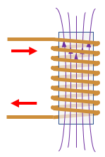
The magnetic flux is proportional to the current through the coil:
Flux = Inductance x CurrentThe constant of proportionality is called the inductance (units: webers per amp, or henrys). In this example, the inductance is 20 webers per amp, or 20 henrys.
60 webers = 20 henrys x 3 amps
Consider change over time:
(change in Flux over time) = Inductance x (change in Current over time)
The change in flux over time is equal the voltage applied (per Maxwell's equations):
Voltage = Inductance x (di/dt)The notation di/dt means the change in current over time (units: coulombs per second per second, or amps per second).
For example, if you apply a 20 volts the inductor, the flow rate increases by one amp per second.
20 volts = 20 henrys x 1 amp/secondTo summarize:
- Applying a 20 volts to the inductor causes the current
to increase by 1 amp for each second that the voltage is
applied.
- Applying zero volts causes the current to continue at a
constant rate.
- Applying -20 volts causes the current to decrease by 1
amp for each second that the negative voltage is applied.
Energy Stored in an Inductor
You might recall from your Physics 1 class that kinetic energy if a moving object is proportional to the square of its velocity. The same principle applies to an inductor. The energy stored in the flywheel of the hydraulic inductor, or the magnetic flux of the electronic inductor, is proportional to the square of the flow rate:Energy = 1/2 x Inductance x Flow-Rate2 (hydraulic)For the hydraulic inductor, the stored energy comes from the pump that pushed the water through the inductor and accelerated the flywheel. For the electronic inductor, the stored energy comes from the battery that pushed the charge through the inductor and built up the magnetic flux through the coil.
Energy = 1/2 x Inductance x Current2 (electronic)
You can extract the energy as heat by connecting a resistor between the two ends of the inductor. This causes a voltage to develop across the resistor and current to flow through it. The voltage and current decay exponentially until the flux reaches zero and all the energy is dissipated as heat in the resistor.
Effects of Ferromagnetic Materials
Inductor-Capacitor (L-C) Oscillator
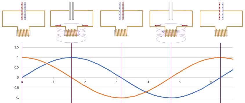
Connecting a capacitor to an inductor creates an oscillator. Once started, charge flows back and forth between the two sides of the capacitor at a fixed frequency, even after peak charge, voltage, and current decrease due to energy loss.
Watch Video
Hydraulic Oscillator
For the hydraulic inductor-capacitor circuit, you start by pumping water into the left side of the capacitor, pressurizing the water. The potential energy is stored in the stretched rubber sheet separating the two sides of the capacitor. You remove the pump and allow the circuit to run freely.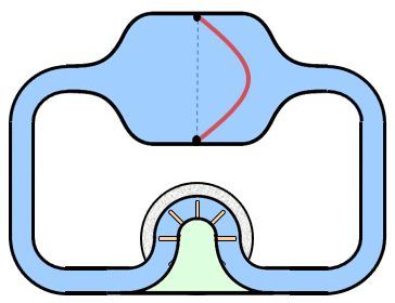
The rubber sheet forces the water through the inductor, causing the inductor's flywheel to spin faster and faster. When the rubber sheet reaches the neutral position, the pressure is zero but the flywheel momentum and current are at their maximum.
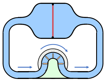
As the flywheel continues to turn, it pressurizes the water and forces it into the opposite side of the capacitor, stretching the rubber sheet in the opposite direction. When the flywheel runs out of energy and stops, the capacitor is fully pressurized in the opposite direction.
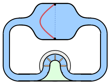
The same process runs in reverse, returning the circuit to the original starting position if there is no friction. With loss of energy to friction, the rubber membrane comes back into a less-stretched maximum position, but it still oscillates with the same period.
Electronic Oscillator
For the electronic inductor-capacitor (L-C) circuit, you start by charging the capacitor, raising the charge to the same voltage as a battery. The potential energy is stored in the electric field that holds the charge on the two sides of the capacitor. You disconnect the battery, connect the capacitor to the inductor, and allow the circuit to run freely.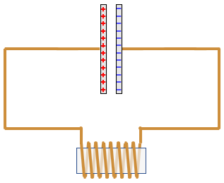
The voltage of the capacitor forces the accumulated charge through the inductor, causing the inductor's magnetic flux to build up. The flux is like the momentum of the flywheel in the hydraulic circuit. When the capacitor runs out of charge, the voltage is zero but the flux and current are at their maximum.
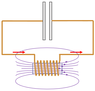
The magnetic flux forces the current to continue flowing into the opposite side of the capacitor, raising the voltage and building up the charge across the capacitor in the opposite direction. When the magnetic flux runs out of energy and the current stops flowing, the capacitor is fully charged in the opposite direction.
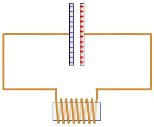
The same process runs in reverse, returning the circuit to the original starting point if there is no loss to wire resistance. With loss of energy to resistance, the capacitor carries less charge at the maximum point, but it still oscillates with the same period.
If you take a charged capacitor as the starting point (time=0), the voltage across the two devices is the cosine function and the current through the circuit is the sine function.

The frequency of the oscillator does not depend on the amount of charge. Charging the capacitor to a higher voltage increases the amplitude of the voltage and current but does not affect the frequency. This is just like a guitar string, which vibrates at the same frequency whether plucked gently or strongly, producing the same note in either case. Only the volume is affected. Like a guitar string, the amplitude dies away due to friction/resistance.
- Period = 2π SQRT(Inductance x Capacitance)
- Frequency = 1/(Period)
L-C Oscillator in a Crystal Radio
The oscillator can be used as a tuner for a crystal radio. The
radio consists of an L-C oscillator, an antenna, a germanium
diode, and an earphone. There is no battery or other internal
power source. The inductor has a ferrite core that can slide
in and out of the coil, which modifies the inductance and
therefore the oscillation frequency. 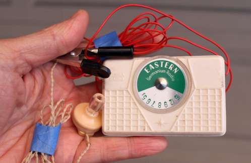
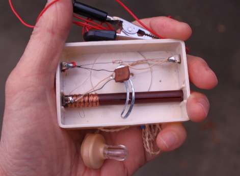
Here is a schematic diagram of the crystal radio circuit:
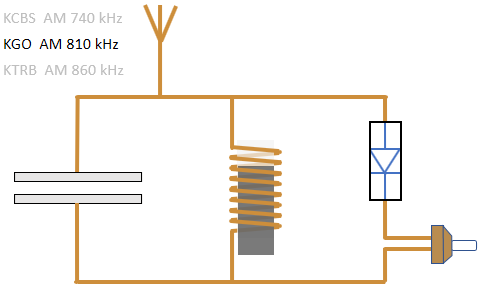
If the inductor-capacitor combination is tuned to oscillate at 810 kHz, the 810 kHz radio signal is maintained in the oscillating circuit, whereas signals from other stations fade out due to wire resistance. The diode converts the amplitude-modulated AM radio signal into an audio signal that can be heard in the earphone.
The energy for the radio comes entirely from the transmitted radio signal; no battery is needed. Only a tiny amount of power from the radio signal is captured by the antenna, so only one person can listen to the faint audio signal through the earphone.
Future topics to be covered:
- How good is the hydraulic analogy?
- Kirchhoff's Laws
- Comparison of capacitor and inductor behavior
- Dielectric materials in capacitors
- Ferromagnetic materials in inductors
- Exponential decay in RC and RL circuits
- Diode behavior
- Alternating current
- Voltage transformer
- Power transmission
Water circuit analogy to electric circuit
from HyperPhysics by C. Rod Nave, Georgia State University
Excellent resource for physics students
Hydraulic analogy, Wikipedia
Brief Wikipedia article, good overview
Understanding Electricity with Hydraulics
Describes hydraulic models for diodes, transistors, and op amps
Circuit Analysis, Khan Academy
Math analysis of electric circuits, including LC oscillator
Crystal radio, Wikipedia
Good info on crystal radio operation and history

