Electronic Inductor and the Hydraulic Analogy
Easy-to-Understand Inductor
Models
for Physics & Engineering Students
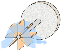
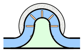
A hydraulic inductor is a water wheel connected through a rigid axle to a heavy stone flywheel, with a housing that forces the water in a clockwise direction when the water flows from left to right. Here's a conceptual view and a cross-section side view:


Applying pressure to the inductor presses water against the paddles of the water wheel. This starts the turning of the water wheel and the connected flywheel. As pressure is applied over time, the flywheel gradually turns faster and faster. Once the flywheel is turning, it tends to keep turning even when the pressure is removed, keeping the water flowing at a constant speed in the absence of outside forces.
Recall that the momentum of a moving object is proportional to the mass and speed of motion. Therefore, the momentum of the flywheel is proportional to the flow rate:
Momentum = Inductance x Flow RateThe constant of proportionality is called the inductance. In this example, the inductance is 20 units.
20 kPa-sec = 20 kPa-sec/LPS x 1 LPS
40 kPa-sec = 20 kPa-sec/LPS x 2 LPS
60 kPa-sec = 20 kPa-sec/LPS x 3 LPS
Consider change over time:
(change in Momentum over time) = Inductance x (change in Flow Rate over time)
The change in momentum over time is the same as the pressure applied:
Pressure = Inductance x (dF/dt)The notation dF/dt means the change in flow rate over time (units: liters per second per second).
For example, if you apply a pressure of 20 kPa the inductor, the flow rate increases by one LPS per second.
20 kPa= 20 kPa-sec/LPS x 1 LPS/secondTo summarize:
- Applying a constant pressure of 20 kPa to the inductor
causes the flow rate to increase by 1 liter per second for
each second
that the pressure is applied.
- Applying zero pressure causes the flow to
continue at a constant rate.
- Applying a negative pressure of 20 kPa causes the flow to decrease by 1 liter per second for each second that the negative pressure is applied.

If the people are in a big hurry, they push on the revolving door (apply positive pressure), which causes the door to speed up and gain momentum.
If the people are relaxed and walk through at the same speed that the door is moving, the door keeps turning at the same speed and has a constant momentum.
If some very slow people come through, the door catches up to them and pushes them through (negative pressure), which causes the door to slow down and lose momentum.
Electronic Inductor
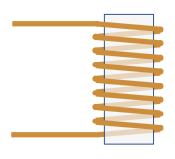
An electronic inductor is a coil of wire wrapped around a cylindrical core.
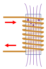
Applying a voltage to the inductor causes magnetic flux to build up in the coil. Magnetic flux is just like the momentum of the flywheel in the hydraulic inductor, and applying a positive voltage is like people in a hurry pushing on the revolving door.
As the voltage is applied over time, the magnetic flux gradually gets larger and larger. Once the magnetic flux is built up, it tends to keep the current flowing even when the voltage source is removed, keeping the current constant in the absence of outside forces.

The magnetic flux is proportional to the current through the coil:
Flux = Inductance x CurrentThe constant of proportionality is called the inductance (units: webers per amp, or henrys). In this example, the inductance is 20 webers per amp, or 20 henrys.
20 webers = 20 henrys x 1 amp
40 webers = 20 henrys x 2 amps
60 webers = 20 henrys x 3 amps
Consider change over time:
(change in Flux over time) = Inductance x (change in Current over time)
The change in flux over time is equal the voltage applied (per Maxwell's equations):
Voltage = Inductance x (di/dt)The notation di/dt means the change in current over time (units: coulombs per second per second, or amps per second).
This is the same equation you see in your physics textbook: V=L(di/dt)
For example, if you apply a 20 volts the inductor, the flow rate increases by one amp per second.
20 volts = 20 henrys x 1 amp/secondTo summarize:
- Applying a 20 volts to the inductor
causes the current to increase by 1 amp for each second
that the voltage is applied.
- Applying zero volts causes the current to
continue at a constant rate.
- Applying -20 volts causes the current to decrease by 1
amp for each second
that the negative voltage is applied.
Energy Stored in an Inductor
You might recall from your Physics 1 class that kinetic energy if a moving object is proportional to the square of its velocity. The same principle applies to an inductor. The energy stored in the flywheel of the hydraulic inductor, or the magnetic flux of the electronic inductor, is proportional to the square of the flow rate:Energy = 1/2 x Inductance x Flow-Rate2 (hydraulic)For the hydraulic inductor, the stored energy comes from the pump that pushed the water through the inductor and accelerated the flywheel. For the electronic inductor, the stored energy comes from the battery that pushed the charge through the inductor and built up the magnetic flux through the coil.
Energy = 1/2 x Inductance x Current2 (electronic)
You can extract the energy as heat by connecting a resistor between the two ends of the inductor. This causes a voltage to develop across the resistor and current to flow through it. The voltage and current decay exponentially until the flux reaches zero and all the energy is dissipated as heat in the resistor.
Ferromagnetic Material Affects Inductance
An inductor works fine with just empty space or air inside the coil. However, real inductors usually have a core inside made of a ferromagnetic material such as iron, which significantly increases the inductance. The iron makes the magnetic field much stronger, which increases the amount of flux in the core.Putting an iron rod inside the coil is like changing the hydraulic inductor flywheel from stone to solid gold. Gold is much heavier than stone, so it is much harder to get spinning, and once started, much harder to stop.
This is how the traffic sensors work at a stop light. There is a large loop of wire buried under the street in each car lane. You can usually see where a large "O" shape has been cut through the asphalt, and a wire loop has been placed in the cut, and then the cut filled in with some black material.
When a car passes over or stops over the loop, the iron in the vehicle increases the inductance of the loop. The stoplight controller monitors the loop inductance to find out whether a vehicle is present.
Inductor-Capacitor (LC) Oscillator Hydraulic Analogy
Back to Main Hydraulic Analogy Page
Water circuit analogy to electric circuit
from HyperPhysics by C. Rod Nave, Georgia State University
Excellent resource for physics students
Hydraulic analogy, Wikipedia
Brief Wikipedia article, good overview
Understanding Electricity with Hydraulics
Describes hydraulic models for diodes, transistors, and op amps
Circuit Analysis, Khan Academy
Math analysis of electric circuits, including LC oscillator